
Views: 0 Author: Site Editor Publish Time: 2026-09-09 Origin: Site


Hydronic underfloor heating relies heavily on precise flow rates and accurate supply temperatures. Getting these variables right determines whether a floor heats evenly or fails entirely. Unlike electric setups, water-based architectures require careful hydraulic planning. The core technical problem comes down to specifying the correct manifold configuration. Installing a pump when it is not needed creates hydraulic conflicts and wastes electrical energy. Omitting a pump when your system requires one leads to insufficient head pressure, cold spots, and damaged floor finishes from excessive water temperatures.
We will evaluate exactly when a project demands an underfloor heating manifold with pump—acting as a secondary control unit—and when a pump-less primary manifold is the superior choice. You will learn how heat sources, system architecture, and pressure drop calculations dictate this engineering decision. This guide provides the technical framework to match your manifold configuration directly to your heat source and building hydraulics.
Heat Source Dictates Design: High-temperature sources (traditional boilers) almost always require a manifold with a pump and blending valve to reduce water temperature, whereas low-temperature sources (heat pumps) typically utilize pump-less manifolds.
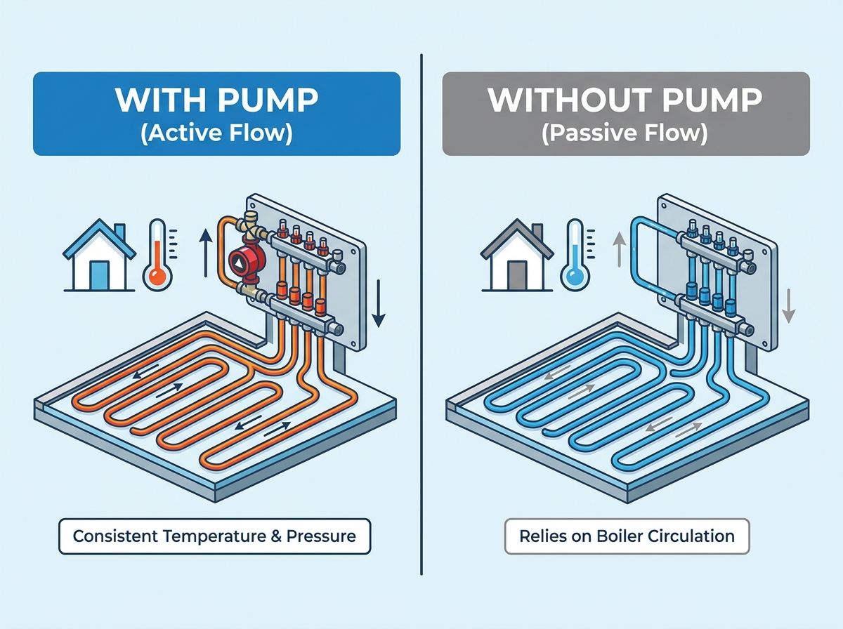
Primary vs. Secondary Systems: A pump-less setup acts as a "primary system" relying on the main heat source circulator, while adding a pump creates a "secondary system" requiring careful hydraulic separation.
Hydraulic Separation is Critical: Adding a secondary pump at the manifold requires careful hydraulic balancing to prevent conflicts with the primary system pump.
System Scale Matters: Large floor areas with long pipe runs create high pressure drops, often necessitating a dedicated manifold pump regardless of the heat source.
Energy Efficiency: Pump-less systems reduce parasitic electrical draw and, when paired with heat pumps, can operate up to 40% more efficiently than traditional boiler and radiator systems.
Table of Contents
A secondary manifold system consists of three main components: the distribution headers, the circulation pump, and the thermostatic mixing valve. The headers distribute water into the individual floor loops. The pump drives the water through these specific loops. The mixing valve regulates the exact temperature entering the floor.
The primary function of this setup is decoupling the floor circuit from the main heating loop. Traditional boilers generate water at roughly 75°C. Sending this directly into a floor damages the screed and warps timber finishes. The mixing valve reduces this supply temperature to a safe 45°C. It achieves this by blending the hot supply water with cooler return water from the floor loops. The localized pump then provides the necessary head pressure to push this blended water through dense pipe networks.
Installers typically mount the pump on the flow side of the injection circuit. This placement ensures optimal distribution. It pulls the blended water directly from the mixing valve and forces it into the flow header. This mechanical arrangement guarantees efficient mixing and maintains a steady flow rate across all active ports.
Here is the exact sequence of operation for a secondary manifold system:
High-temperature water arrives from the primary boiler circuit at the manifold injection valve.
The thermostatic mixing valve senses the current flow temperature and opens the hot port to admit primary water.
The local circulator pump pulls this hot water, mixing it with cooler water returning from the floor loops.
The blended, temperature-safe water enters the flow header and distributes through the flow meters into the floor.
Excess return water that is not recirculated gets pushed back into the primary return pipework to head back to the boiler.
Component Breakdown: Secondary vs. Primary Manifolds | ||
Component | Secondary System (With Pump) | Primary System (Pump-Less) |
|---|---|---|
Circulator Pump | Integrated directly onto the manifold assembly. | Relies entirely on the central plant room pump. |
Mixing Valve | Included. Blends hot supply with cool return. | Absent. Requires pre-mixed water from the source. |
Flow Meters | Included on the flow header for visual balancing. | Included on the flow header for visual balancing. |
Actuators | Mounted on the return header for zone control. | Mounted on the return header for zone control. |

A pump-less manifold operates as a direct extension of the primary heating circuit. It features standard flow and return headers. It includes flow meters for visual balancing and electro-thermic actuators for zone control. It lacks a dedicated local pump and a mixing valve. It relies entirely on the primary system pump located at the heat source or in the plant room.
This configuration has strict operational requirements. The water arriving at the manifold must already be at the correct design temperature. The primary heat source must regulate this temperature before the water travels to the manifold. The primary pump must possess sufficient residual pressure. It needs enough power to overcome the friction loss of the entire distribution pipework plus the individual underfloor heating circuits.
Installers use pump-less manifolds when the building architecture supports centralized distribution. If the main circulator can push 15 liters per minute at a 40kPa pressure drop, and the floor circuits only require 12 liters per minute at 25kPa, a local pump is redundant hardware.
Traditional boilers require a manifold pump and mixing unit. These heat sources operate at high temperatures to prevent internal condensation and heat domestic hot water. You must reduce this temperature before it enters the floor network. Failing to do so causes catastrophic floor failure. Concrete screeds crack under thermal stress. Engineered wood floors warp, cup, and split.
The integrated mixing valve and pump work together to protect the floor. The pump continuously circulates water through the floor loops. As the water transfers heat to the room, it cools down. It returns to the manifold at a lower temperature. The mixing valve takes a small amount of 75°C boiler water and injects it into this cooler return water. This precise blending process maintains a constant, safe flow temperature of 45°C into the floor.
Heat Source Output vs. Floor Temperature Limits | |||
Heat Source Type | Typical Output Temperature | Maximum Safe Floor Temp (Screed/Timber) | Manifold Configuration Required |
|---|---|---|---|
Gas/Oil Boiler | 70°C - 80°C | 45°C - 50°C | With Pump & Mixing Valve |
Biomass Boiler | 75°C - 85°C | 45°C - 50°C | With Pump & Mixing Valve |
Air Source Heat Pump | 35°C - 45°C | 45°C - 50°C | Pump-Less (Direct) |
Many renovation projects involve retrofitting underfloor heating into an existing radiator system. Radiators require high water temperatures to output sufficient heat. Underfloor heating requires low temperatures. You cannot run both emitters on the same direct circuit without compromising one of them.
A manifold mixing unit solves this problem. It allows the primary circuit to run hot. The radiators receive the 75°C water they need. The manifold taps into this hot primary loop. The local pump and blending valve step the temperature down for the floor extension. This creates a secondary circuit. The underfloor heating operates safely at a lower temperature while the rest of the house utilizes the high-temperature primary loop.
When retrofitting a mixed-emitter system, follow these specific steps:
Identify the primary flow and return pipes serving the nearest radiator circuit.
Tee off these primary pipes to create a supply branch for the new floor zone.
Install a two-port motorized zone valve on the new branch to isolate the floor when demand is met.
Connect the branch to the injection ports of the underfloor heating manifold with pump.
Wire the manifold pump and zone valve to the local room thermostat via a wiring center.
Large floor areas present significant hydraulic challenges. Extensive pipe runs create high friction losses. Circuits exceeding 100 meters restrict water movement heavily. High-density pipe spacing further increases this resistance. A central boiler pump often struggles to push water through these restrictive networks.
A localized manifold pump overcomes this pressure drop. It guarantees an adequate flow rate across all loops. When the primary pump is undersized for the total system volume, the manifold pump takes over the heavy lifting for that specific zone. It ensures every circuit receives the required liters per minute. This prevents cold spots at the far ends of the room and ensures even heat distribution across large open-plan spaces.
Heat pumps operate fundamentally differently from traditional boilers. They are optimized for low-temperature output. They utilize weather compensation to deliver water directly at 35°C to 45°C. This matches the exact temperature requirements of underfloor heating. You do not need to reduce the temperature at the manifold.
Using a mixing valve and secondary pump with a heat pump causes massive efficiency losses. Forcing a heat pump to generate higher temperatures just to blend them down wastes electrical energy. A streamlined, direct-to-floor setup eliminates this waste. Pump-less manifolds allow the heat pump to operate at its highest coefficient of performance. This direct approach can operate up to 40% more efficiently than traditional high-temperature blending systems.
Modern plant room designs often utilize a central, variable-speed primary pump. This single pump handles the entire building's circulation. It modulates its speed based on system demand. In these architectures, adding local pumps at every manifold creates unnecessary complexity.
Installers use buffer tanks or low-loss headers to manage the hydraulics. The buffer tank provides hydraulic separation between the heat source and the distribution network. The central primary pump pulls from this tank and pushes water directly to the pump-less manifolds. The manifolds simply distribute the flow. They do not need to generate local head pressure. This centralized pumping strategy simplifies maintenance and reduces the number of moving parts in the building.
Small extensions or single-room setups rarely require a dedicated manifold pump. A small bathroom or kitchen addition usually involves short pipe runs. The pressure drop across these short circuits is minimal.
The existing primary pump typically has sufficient residual head to cover this minor additional resistance. You can pipe a small pump-less manifold directly into the existing heating circuit. You must ensure the water temperature is appropriate for the floor finish. If the temperature is correct, omitting the secondary pump simplifies the installation and reduces unnecessary hardware.
A manifold with a pump provides high precision. The localized mixing valve reacts instantly to temperature changes. It offers fail-safe mechanical limits. If the primary system sends dangerously hot water, the blending valve shuts down the injection port. It protects the floor finish entirely independently of the main boiler controls.
A pump-less manifold relies entirely on central plant controls. The heat source must regulate the temperature perfectly. If a heat pump sensor fails or a central mixing valve sticks, high-temperature water flows directly into the floor network. This presents a higher risk for sensitive floor finishes. Installers often add a separate high-limit mechanical thermostat to the primary pipework to cut power to the zone valves if temperatures spike.
Secondary systems with local pumps are easier to balance locally. The manifold pump guarantees flow through the floor loops regardless of what other zones in the building are doing. If a radiator zone opens or closes, the underfloor heating flow rate remains stable. The local pump isolates the floor from pressure fluctuations in the primary circuit.
Pump-less systems require rigorous whole-house hydraulic balancing. Every zone interacts with the others. If domestic hot water priority activates, the flow to the underfloor heating might stop entirely. If a large radiator zone opens, it can starve the floor manifold of pressure. Installers must carefully calculate pipe sizes and install balancing valves on the primary branches to ensure the pump-less manifold receives adequate flow under all operating conditions.
Systems utilizing a manifold pump require more components. You must install the pump, the mixing valve, and the associated isolation valves. This increases the initial hardware list. The extra pump creates a continuous parasitic electrical draw. Every time the floor zone calls for heat, the local pump consumes electricity. This adds to the ongoing energy requirements of the building. It also introduces another mechanical component that requires future maintenance.
Pump-less manifolds offer a highly streamlined approach. They require fewer parts. Operation is highly energy-efficient because you eliminate the electrical draw of secondary pumps. You remove the hardware burden of localized mixing units. For compatible low-temperature heat sources, this stripped-back architecture provides a highly efficient and reliable heating distribution method.
Placing a manifold pump in series with a primary pump causes severe issues. If you do not provide proper hydraulic separation, the two pumps fight each other. They attempt to pull and push water at different rates. This leads to flow erraticism. The pumps can experience cavitation, where pressure drops cause water to vaporize and damage the impellers. This results in premature pump failure and noisy pipework.
You must decouple the primary and secondary circuits. Utilize low-loss headers or buffer vessels in the plant room. If space is limited, install closely spaced tees near the manifold. These hydraulic separators allow the primary pump to circulate water past the manifold without forcing it through. The manifold pump can then draw exactly what it needs from the separator without fighting the primary circulator.
To properly install closely spaced tees for hydraulic separation:
Identify the primary flow and return lines near the manifold location.
Install two tee fittings on the primary loop, keeping them a maximum of four pipe diameters apart.
Connect the supply side of the manifold pump to the first tee.
Connect the return side of the manifold to the second tee.
Ensure the primary loop continues past the tees to serve other zones or return to the boiler.
Installers sometimes assume the primary circulator can handle the underfloor heating pressure drop. They install a pump-less manifold without checking the math. The primary pump fails to push enough water through the dense floor loops. The flow meters barely register movement. The system fails to reach design room temperatures, leaving the client with a cold house.
You must perform accurate pipe sizing. Calculate the pressure drop of the index circuit. The index circuit is the longest and most restrictive pipe run in the system. Verify the primary pump's performance curve. Ensure the pump can deliver the required total flow rate at the calculated pressure drop. If the pump curve falls short, you must either upgrade the central pump or switch to a manifold with a local pump.
Follow these steps to verify primary pump capacity:
Measure the length of the longest underfloor heating loop (the index circuit).
Calculate the friction loss for that specific pipe diameter and length (usually measured in kPa or meters of head).
Add the pressure drop of the manifold valves and the primary distribution pipework.
Calculate the total required flow rate for all floor loops combined (in liters per minute).
Plot these two figures (Total Head and Total Flow) on the primary pump's performance chart to ensure it falls within the operational curve.
Specifying a manifold control pack based solely on the number of ports is a common mistake. The blending valve has a specific Kv value. This value represents its flow coefficient. If the Kv value is too small, the valve cannot pass enough hot water to meet the heat load of the room. The pump will circulate water, but the floor will never reach the required temperature.
You must match the manifold control pack specifications to the exact kW heat loss of the zone. Calculate the heat loss of the space. Determine the required flow rate to satisfy that heat loss at your specific design temperatures. Check the manufacturer's data for the mixing valve. Ensure its Kv rating can handle the required flow rate at the available pressure. Do not guess valve sizes based on manifold length.
Mixing Valve Kv Sizing Guide | ||
Zone Heat Loss (kW) | Required Flow Rate (L/min) | Recommended Minimum Valve Kv |
|---|---|---|
Up to 5 kW | Approx. 5 - 7 L/min | 1.0 - 1.5 |
5 kW to 10 kW | Approx. 8 - 14 L/min | 2.0 - 2.5 |
10 kW to 15 kW | Approx. 15 - 21 L/min | 3.0 - 3.5 |
Over 15 kW | 22+ L/min | 4.0+ (or multiple manifolds) |
Choosing between a pumped or pump-less manifold is a strict technical requirement dictated by your heat source temperature and system hydraulics. High-temperature boilers and mixed-emitter systems demand local mixing and pumping to protect floors and ensure flow. Low-temperature heat pumps and centrally managed architectures perform best with streamlined, pump-less manifolds.
Calculate your total system pressure drop to determine if your primary pump can handle the floor circuits without local assistance.
Verify your heat source output temperature to confirm if localized blending is mandatory for floor protection.
Install hydraulic separation using low-loss headers or closely spaced tees whenever you add a secondary pump to a primary circuit.
Match the mixing valve Kv rating directly to the kW heat loss of the zone to prevent flow restriction.
A: No. Heat pumps generate low-temperature water (35°C–45°C) ideal for direct floor heating. Using a pump and mixing valve reduces system efficiency. A pump-less manifold allows the heat pump to operate directly, maximizing energy performance.
A: The pump should be mounted on the flow side of the injection circuit. It pulls blended water from the thermostatic mixing valve and pushes it directly into the flow header, ensuring even distribution across all pipe loops.
A: Yes. Most standard pump-less manifolds can be retrofitted with a bolt-on control pack. You attach the mixing valve and pump assembly to the primary flow and return connections on the side of the existing headers.
A: A primary system uses a pump-less manifold and relies entirely on the main heat source pump. A secondary system uses a manifold with its own local pump and mixing valve, hydraulically separated from the main building circuit.
A: A constantly running pump usually indicates a wiring fault or a failed relay in the wiring center. The pump should only activate when a room thermostat calls for heat and opens the corresponding manifold actuators.
A: A standard domestic manifold pump typically handles up to 12 loops, covering roughly 120 to 150 square meters. Larger areas require heavy-duty commercial pumps or multiple manifold stations to maintain adequate flow.
A: Running 75°C boiler water directly into a floor without a mixing valve will cause severe damage. Concrete screeds will crack, timber floors will warp, and the surface temperature will become dangerously hot to walk on.


