
Views: 0 Author: Site Editor Publish Time: 2026-09-09 Origin: Site


Think of any modern hydronic radiant setup. You quickly realize one component acts as its central nervous system. Hidden beneath floorboards or inside utility cabinets, this unit controls everything. Piping simply delivers heated water across a room. A central hub actually dictates system efficiency, temperature control, and zonal accuracy. If these controls fail, your radiant floors fail to deliver comfort. For contractors, developers, and homeowners at the procurement stage, grasping exactly how does underfloor heating manifold work is a fundamental prerequisite. This knowledge lets you evaluate component quality reliably. It ensures strict compatibility across various heat sources, including modern heat pumps and traditional boilers. Furthermore, understanding this core mechanism prevents long-term maintenance liabilities. Read on to discover the fluid dynamics, component anatomy, and calibration techniques essential for peak performance.
The manifold regulates water flow, temperature, and pressure across multiple independent heating zones (loops).
A fully optimized manifold system requires precise calibration of flow meters and mixing valves to maintain a stable Delta T (temperature drop).
Material selection (stainless steel vs. brass) dictates long-term corrosion resistance and lifecycle costs.
Integrating smart actuators at the manifold level is essential for room-by-room climate control and operational cost-efficiency.
Correct initial balancing and pressure testing are non-negotiable steps to prevent cold spots and system airlocks.
Table of Contents
Understanding the exact fluid dynamics inside your heating system justifies the manifold's central role. A boiler or heat pump generates raw thermal energy. However, this energy is often too intense or poorly distributed for direct floor application. The manifold acts as a thermal translator. It scales down high temperatures and distributes fluid evenly across complex pipe networks. We can break this thermal regulation process into three distinct phases.
The Supply Phase (Flow): High-temperature water from your primary heat source enters the flow manifold. Boilers often output water at 70°C to 80°C. Pushing this directly into floor pipes would damage the screed and warp floor finishes. A blending or mixing valve intervenes here. It combines this boiling supply with cooler return water. This reduces the water temperature to safe, floor-compatible levels. Installers typically set this between 35°C and 45°C.
The Distribution Phase: Once properly mixed, the water enters the top distribution bar. Here, the system divides the fluid into individual loops. Different rooms contain differing pipe lengths. A large living room might require 100 meters of piping, while a small bathroom needs only 20 meters. You must apply varied flow rates to achieve uniform heating across these mismatched zones.
The Return Phase: Cooler water eventually flows back to the return manifold after transferring its heat to the floor. The system does not waste this fluid. It recirculates a portion back into the mixing valve to maximize energy efficiency. The remaining water travels back to the boiler or heat pump for reheating. This closed-loop cycle guarantees continuous thermal stability.
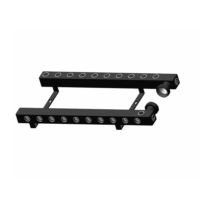
Buyers must evaluate manifolds based on hardware quality and modularity. An underfloor heating manifold is not a single solid block. It is a highly engineered assembly of specialized valves and gauges. Familiarity with these specific parts ensures you purchase a durable, easily serviceable unit.
Flow meters sit on the top supply bar of the unit. These act as visual indicators for installers and maintenance teams. They allow you to manually adjust the volume of water entering each zone. We measure this volume in liters per minute (L/min). When buying a unit, look closely at the flow meter design. You want easily readable, durable flow meters featuring anti-fouling designs. Poorly manufactured meters quickly become opaque, making future calibration impossible.
The bottom return bar houses the thermostatic valves. You attach electromechanical actuators to these valves. Actuators open or close individual pipe loops based on signals from connected room thermostats. They serve as the digital bridge between user preferences and physical water flow. Your primary buying criterion here involves compatibility. Ensure your chosen actuators match your low-voltage smart thermostats. Also, consider their reaction time and default resting state, choosing between normally open or normally closed variants.
Hydronic systems naturally accumulate trapped air over time. Air bubbles create blockages, severely hindering heat transfer. Air vents and drain valves sit at the end of the manifold bars to bleed this trapped air. Installers use the fill valves to introduce water and pressure into the system initially. Industry best practices highly recommend selecting auto-air vents. These automatic versions reduce manual maintenance demands. They also proactively prevent cavitation inside the circulating pump.
Many manifolds come paired with a dedicated circulating pump and mixing unit. The primary boiler pump rarely possesses the strength to push water through hundreds of meters of micro-bore floor pipes. The manifold pump ensures adequate pressure head across all micro-loops. It operates completely independently of the primary heat source pump. Look for highly efficient, variable-speed pumps designed to adjust their output based on active heating zones.
Procurement decisions often hinge on material selection. Manufacturers primarily build these systems using either stainless steel or brass. Your choice impacts budget, compatibility with local water quality, and long-term scalability. Comparing these two industry standards guides buyers toward the right investment.
Stainless Steel Manifolds
Stainless steel represents the modern standard for premium installations. It offers exceptional corrosion resistance due to its natural chromium oxide layer. These units weigh less than brass alternatives. They also feature a slightly larger internal bore, providing slightly better fluid dynamics. Experts consider stainless steel ideal for larger commercial projects or high-end residential systems. However, they carry distinct disadvantages. They are generally more expensive. Furthermore, they require precision manufacturing. Poor quality welds on cheaper stainless units can lead to microscopic leaks over time.
Brass Manifolds
Brass stands as the traditional heavy-duty choice. It boasts decades of proven field reliability. Brass units feel incredibly solid and are often more cost-effective for standard, smaller installations. The thick metal walls handle high pressure effortlessly. Despite these strengths, brass carries a notable vulnerability. It remains susceptible to dezincification. If your system water pH is not properly treated, the zinc inside the brass alloy degrades. This creates a brittle, porous structure prone to sudden failure.
Selection Logic
We recommend choosing materials based on local water hardness, total system size, and warranty expectations. Use stainless steel in hard water areas or when integrating complex heat pump systems. Rely on brass for smaller domestic retrofits where budget constraints prioritize immediate affordability over industrial-grade fluid dynamics.
Material Comparison Chart: Stainless Steel vs. Brass
Material Attribute | Stainless Steel | Brass |
|---|---|---|
Corrosion Resistance | Excellent (Resists scaling and rust) | Moderate (Vulnerable to dezincification) |
Weight & Handling | Lighter, easier wall mounting | Heavy-duty, requires robust brackets |
Flow Dynamics | Higher efficiency due to larger internal bore | Standard efficiency |
Cost Profile | Premium pricing | Highly cost-effective |
Ideal Application | Large commercial & heat pump systems | Standard domestic heating layouts |
Installing top-tier hardware only solves half the puzzle. You must connect the physical operation of the manifold to long-term energy savings. A poorly calibrated system wastes energy, regardless of how efficient the heat pump claims to be. We call the solution to this problem "system balancing."
Consider the concept of balancing closely. Imagine a large kitchen loop measuring 110 meters, alongside a tiny bathroom loop measuring just 25 meters. Water naturally seeks the path of least resistance. Without intervention, the water rushes through the short bathroom loop, returning to the boiler quickly. The long kitchen loop receives almost no flow, leaving the floor cold. To output the same heat per square meter, the longest pipe requires a significantly higher flow rate than the shortest loop. Installers balance the system by restricting flow to the short loops via the flow meters.
Energy efficiency realities mandate this exact calibration. Unbalanced manifolds force heat pumps or boilers to overwork. The primary heater stays on longer to force heat into the starved kitchen loop. This continuous running destroys the cost-effectiveness of the entire heating system. You end up paying exorbitant energy bills for uneven comfort.
You can verify a properly functioning manifold by checking specific metrics for success:
Stable Flow Rates: Red indicators inside the flow meters should hold steady at their calculated L/min marks.
Target Delta T: The system must maintain a consistent temperature drop (Delta T) between the flow and return pipes.
Optimal Range: A properly balanced system aims for a Delta T of around 5°C to 10°C.
Uniform Floor Temperatures: Thermal imaging should reveal even heat distribution without distinct cold patches.
Knowing what goes wrong during rollout demonstrates true practical expertise. Hydronic radiant heating involves burying pressurized pipes under heavy concrete or screed. You cannot easily fix mistakes once the floor hardens. Highlighting these lifecycle realities guides better installation practices.
Pre-screed pressure testing represents an absolute necessity. You must pressurize the manifold and all connected loops before pouring the floor screed. Installers typically use air or water to pump the system up to several bars of pressure. They monitor the pressure gauge for at least 24 hours. A dropping gauge identifies fatal leaks. Finding a leak at this stage requires a simple pipe splice. Finding a leak after the concrete cures requires jackhammers and immense repair bills.
Even perfectly installed systems encounter operational hurdles over their lifecycle. Prepare for these common failure points:
Airlocks: Trapped air blocks water flow, causing distinct cold zones in certain rooms. The solution involves the proper use of the purge valves to bleed the system.
Stuck Actuators: Valve pins frequently seize inside the manifold after long summer downtimes. A gentle tap or manual reset usually frees the stuck pin.
Cloudy Flow Meters: A lack of system inhibitor leads to biological algae growth or magnetite sludge. This turns the water brown and stains the flow meters.
Preventative care extends hardware life significantly. We highly recommend an annual routine maintenance schedule. Start with a comprehensive visual inspection for weep leaks around joints. Next, perform a system pressure check to ensure it sits between 1.0 and 1.5 bar. Finally, prioritize water treatment. Top up the chemical inhibitor annually to prevent sludge buildup and internal corrosion.
Common Diagnostic Chart: Manifold Troubleshooting
Symptom | Probable Cause | Recommended Action |
|---|---|---|
Entire floor remains cold | Mixing valve closed / Pump failure | Check thermostat demand; test pump power. |
One specific room is cold | Stuck actuator pin / Airlock | Remove actuator, manually press pin; bleed air vent. |
Brown water in flow meters | Magnetite sludge buildup | Perform chemical power flush; add inhibitor. |
System pressure drops frequently | Micro-leak at manifold fittings | Inspect eurocone connections; tighten loose nuts. |
Understanding how a heating manifold functions takes the guesswork out of system design. It acts as the mechanical brain of your radiant floors. It translates raw thermal energy into precise, room-by-room comfort. You now know how blending valves regulate supply temperatures safely. You also understand why balancing individual pipe loops guarantees optimal energy efficiency.
When shortlisting equipment, remember to evaluate units based on strict operational parameters. Select models based on exact port requirements to match your home's zones. Scrutinize material suitability, weighing stainless steel against brass based on your local water quality. Furthermore, verify integration capabilities with your existing smart home technology and heat pump specifications.
Take action today to secure a flawless heating installation. Review your architectural floor plans and system schematics closely. Consult with a qualified hydronic engineer to map out your specific zoning requirements. Finally, request a detailed quote for a pre-assembled manifold unit tailored exactly to your building's unique thermal profile.
A: Yes, in most cases. Unless the heating area is exceptionally small, a dedicated manifold pump is required. Examples of small areas include a single bathroom branched off an existing radiator circuit. Larger spaces feature hundreds of meters of micro-bore floor pipes. The primary boiler pump cannot overcome this high flow resistance alone.
A: Cloudy meters usually indicate a buildup of magnetite, commonly known as sludge. It can also indicate algae growth inside the system. This suggests the system was not properly flushed during installation. It also implies the water lacks sufficient chemical inhibitor to prevent bacterial growth and internal rust.
A: You typically adjust it by removing the protective locking cap on the top flow meter. You then manually twist the internal valve assembly. Watch the internal red indicator inside the glass. Keep twisting until this indicator aligns with the specific liters-per-minute (L/min) calculation required for that heating loop.
A: Yes, standard manifolds can accommodate up to 12 distinct ports or zones. This handles a substantial square footage. However, for larger properties or multi-story homes, best practice dictates a different approach. You should install one separate manifold per floor. This optimizes pressure delivery and simplifies local temperature control.


