
Views: 0 Author: Site Editor Publish Time: 2026-06-29 Origin: Site


Improperly sized expansion vessels present major operational risks in closed-loop systems. They often trigger frequent boiler lockouts, pressure relief valve discharges, and premature component fatigue. When system pressure fluctuates wildly, operators face constant maintenance headaches and potential catastrophic failures. Exact engineering calculations remain mandated for commercial specifications. However, industry professionals routinely rely on established baselines for initial feasibility, space planning, and rapid troubleshooting on site. You need a reliable starting point before diving into complex thermal dynamics. This guide breaks down the universally accepted rule of thumb for sizing these crucial components. We identify the threshold where baseline estimates must transition into precise thermal formulas. Finally, we outline the strict procurement criteria you need to guarantee long-term system reliability.
The Baseline Estimate: The standard rule of thumb dictates that expansion vessels should hold approximately 10% of the total system water volume.
Application Limits: This 10% rule is strictly for preliminary sizing in standard sealed heating systems; commercial, high-temperature, or chilled water systems require precise calculation models.
Component Differentiation: Evaluating expansion vessels (closed heating) versus pressure vessels (potable water) requires assessing different internal membranes and compliance certifications.
Implementation Matters: Proper installation—including precise pre-charge calibration and appropriate mounting hardware—is as critical to vessel lifespan as accurate volume sizing.
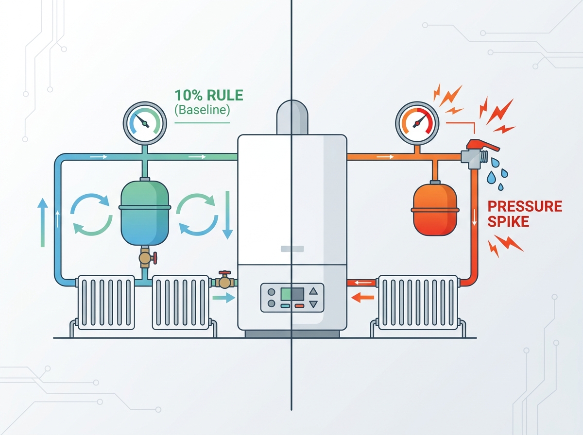
Industry standards often lean on quick mathematical baselines. The universally accepted rule of thumb states your vessel should accommodate 10% of the total system water volume. A 100-liter heating circuit requires a 10-liter vessel. This simple equation relies on standard mathematical assumptions. It assumes a typical flow temperature of around 80°C and a standard static head of roughly one bar.
Contractors and engineers rely heavily on this metric. You can rapidly assess job-site requirements without complex software. It allows immediate spatial footprint planning in tight mechanical rooms. Plumbers can quickly verify if an existing unit looks suspiciously small during routine maintenance. Fast decisions keep projects moving forward efficiently.
Relying solely on guesses carries steep operational costs. Undersized units initiate a dangerous cascading failure loop. Thermal expansion creates rapid pressure spikes during the heating cycle. The pressure relief valve (PRV) then discharges valuable treated system water. Once the system cools, internal pressure drops below the minimum safe operating threshold. This triggers boiler lockouts. Users perform manual top-ups, which introduces fresh oxygenated water. Fresh oxygen rapidly accelerates internal pipework corrosion.
You must abandon this rule under specific edge cases. Solar thermal systems experience extreme high-temperature peaks, expanding fluid far beyond standard heating rates. High-rise buildings generate enormous vertical static pressure, requiring specialized pre-charge parameters. Large commercial cascade systems involve fluid volumes too massive for rough estimations. In these scenarios, the 10% rule guarantees failure.
Professionals must clearly distinguish between closed heating applications and domestic water applications. You cannot use these units interchangeably. We define closed-circuit units as standard expansion tanks. They manage thermal expansion within sealed heating or cooling circuits. Conversely, we define potable units as pressure accumulators. They manage pressure fluctuations in domestic hot or cold water networks.
Material choices dictate compliance. Heating applications handle non-potable water. They typically utilize Styrene-Butadiene Rubber (SBR) or Ethylene Propylene Diene Monomer (EPDM) diaphragms. These materials withstand glycol mixtures and high temperatures. Potable applications require WRAS-approved materials or regional equivalents. They rely on high-grade butyl bladders. Potable units must also feature flow-through designs. This constant water movement prevents stagnation and deadly Legionella bacterial growth.
Specifying the wrong category carries severe consequences. Installing a heating tank on a domestic water line causes immediate compliance failures. The incorrect membrane will degrade rapidly when exposed to chlorine. Worse, stagnant water in dead legs introduces severe health and safety risks.
Feature | Closed Heating Circuit | Potable Hot/Cold Water |
|---|---|---|
Fluid Type | Treated water, glycol mixtures | Clean, safe drinking water |
Membrane Material | SBR or EPDM (Non-potable) | Butyl (WRAS/NSF Approved) |
Internal Design | Single connection, stagnant risk | Flow-through design, prevents Legionella |
Typical Color | Red (commonly) | White or Blue (commonly) |
Engineers must transition from rough estimates to hard evidence for complex projects. The 10% rule provides a safety net, but formal engineering calculations ensure absolute accuracy. Proper math prevents unexpected PRV discharges in large commercial environments.
Accurate sizing demands specific data points. You must gather these core calculation variables before selecting a unit:
Total System Volume ($V_s$): The total water content of the boiler, pipework, and radiators.
Expansion Coefficient ($e$): The physical expansion rate based on maximum operating temperature.
Initial Fill Pressure ($P_i$): The cold fill pressure dictated by the building's vertical static head.
Maximum Operating Pressure ($P_f$): The PRV rating minus a standard 0.5 bar safety margin.
Consider a standard 150-liter heating system operating at a maximum of 80°C. Water at 80°C has an expansion coefficient of roughly 0.029. We assume an initial fill pressure of 1.0 bar (2.0 bar absolute) and a PRV set to 3.0 bar. We limit our maximum final pressure to 2.5 bar (3.5 bar absolute) for safety.
First, calculate the expansion volume: 150 liters multiplied by 0.029 equals 4.35 liters. Next, calculate the acceptance factor. Divide absolute initial pressure (2.0) by absolute final pressure (3.5) to get 0.57. Subtract 0.57 from 1 to get an acceptance factor of 0.43. Finally, divide the expansion volume (4.35) by the acceptance factor (0.43). The actual required volume is exactly 10.1 liters. The 10% rule would suggest 15 liters. The estimate works safely, but formal math proves a smaller unit suffices.
Procurement demands a careful feature-to-outcome analysis. You must assess construction quality to ensure long-term system stability. Poorly manufactured units fail within a few years, causing extensive secondary damage.
Engineers must choose between fixed diaphragms and replaceable bladders. Fixed diaphragms offer lower upfront costs. They work exceptionally well in domestic settings. However, you must replace the entire unit if the membrane fails. Replaceable bladders demand higher capital expenditure initially. Yet, they lower operational maintenance burdens for commercial sites. Technicians can swap a ruptured bladder without discarding the steel shell.
Corrosion resistance remains a critical evaluation metric. Evaluate the outer shell materials carefully. High-quality units feature thick carbon steel with baked epoxy coatings. Check the flange connection quality. Stainless steel flanges outlast galvanized alternatives significantly. Galvanized steel eventually succumbs to aggressive water chemistries.
Gas retention dictates maintenance schedules. expansion vessels rely on a pressurized cushion to absorb water. Some manufacturers pre-charge units with standard compressed air. Premium vendors use pure dry nitrogen. Nitrogen molecules are larger than oxygen molecules. They permeate through the rubber membrane much slower. Nitrogen pre-charges extend the lifespan of the pressure cushion and reduce manual service intervals.
Strategic positioning determines mechanical success. You must install the unit on the return pipework, ideally on the suction side of the circulation pump. This creates a neutral point of pressure. It ensures the pump operates with a positive pressure differential. Incorrect placement on the discharge side often leads to negative pressure zones. This causes dangerous pump cavitation and air ingress.
Thermal protection extends membrane life. You must maintain adequate distance between the primary heat source and the rubber diaphragm. Direct contact with extreme boiler temperatures degrades rubber compounds rapidly. Installing a simple anti-gravity loop or a minor pipework standoff provides sufficient thermal buffering.
Physical securing presents major installation challenges. These units become significantly heavier when fully saturated with water. Wall structures must support this dynamic load. You must specify load-bearing accessories during the design phase. Using a heavy-duty Round Expansion Tank Bracket prevents mechanical stress on copper or composite pipework. Unsupported tanks tear pipe fittings apart, flooding mechanical rooms instantly.
Pre-commissioning checks prevent immediate failures. Installers often forget to check the pre-charge pressure. You must adjust this nitrogen or air cushion before filling the system with water. The pre-charge must match the building's static head. Attempting to adjust gas pressure while the water side is pressurized provides false readings and guarantees faulty operation.
System scalability requires forward-thinking modularity. Engineers frequently debate using one large monolithic unit versus two smaller units installed in parallel. Parallel installations offer superior redundancy. If one membrane ruptures, the system retains partial operational capacity. Smaller units also prove much easier to maneuver through narrow commercial doorways.
Scrutinize manufacturer warranties carefully. Read the fine print before issuing a purchase order. Many vendors advertise five-year warranties. However, they often cover only the steel shell. They might classify the internal rubber membrane as a consumable wear part, limiting its warranty to a single year.
Technical buyers should utilize a strict final checklist. Verify the actual vertical static head of the building. Confirm the specified PRV settings match the design calculations. Ensure your mounting hardware accommodates the wet weight of the unit. Validate these simple metrics to avoid costly rework on site.
Rely on the 10% volumetric rule exclusively for rapid spatial planning and initial job-site feasibility in standard residential systems.
Execute rigorous mathematical calculations for commercial projects, solar thermal circuits, or any system handling extreme temperatures and high static heads.
Specify mounting hardware diligently, as unsupported water weight severely damages pipework and fittings over time.
Validate all pre-charge pressures against the building's vertical height before introducing any water into the network.
Correct specification directly correlates to the longevity, safety, and efficiency of your entire thermal system. Taking shortcuts during the sizing or mounting phases inevitably leads to system lockouts and costly emergency repairs.
A: Pressure loss typically stems from three main causes. The Schrader valve might leak slightly, allowing gas to escape over time. The internal rubber membrane could be ruptured, allowing water to flood the gas chamber. Finally, natural gas permeation occurs slowly as microscopic air molecules migrate through the rubber membrane into the water over several years.
A: You must set the pre-charge pressure to match the building's static head. Measure the vertical height from the vessel to the highest point in the heating system. Ten meters of height equals one bar of pressure. Set the pre-charge exactly 0.2 to 0.3 bar above this static height to maintain a positive pressure at the highest radiator.
A: No, an oversized unit rarely causes operational problems. A slightly larger tank safely reduces system pressure fluctuations and extends component lifespans. Conversely, an undersized unit guarantees rapid pressure spikes, frequent safety valve discharges, and continuous system faults.
A: You should service them annually during routine boiler maintenance. Technicians must isolate the unit from the main heating circuit. They must drain the water side completely to remove backpressure. Finally, they use a standard pressure gauge to test and top up the gas pre-charge via the Schrader valve.


