
Views: 0 Author: Site Editor Publish Time: 2026-06-29 Origin: Site


Thermal expansion creates a hidden, relentless danger inside your residential plumbing network. As water heats up, it naturally expands and immediately looks for an escape route. If it cannot escape, pressure builds rapidly inside the pipes. This phenomenon in modern closed-loop systems causes extreme pressure spikes every single day. These recurring spikes risk premature water heater failure and frequently void expensive manufacturer warranties. Professional plumbers see burst pipes and leaking temperature relief valves constantly because of unmanaged thermal expansion. You must identify the exact, code-compliant location to safely install this critical protective device. We will provide a definitive framework covering connection placement, orientation, and structural support methods. Follow this comprehensive guide to ensure maximum system longevity and effortlessly pass strict municipal plumbing inspections. Protecting your investment starts with understanding these fundamental installation principles. We break down the exact technical requirements needed for success.
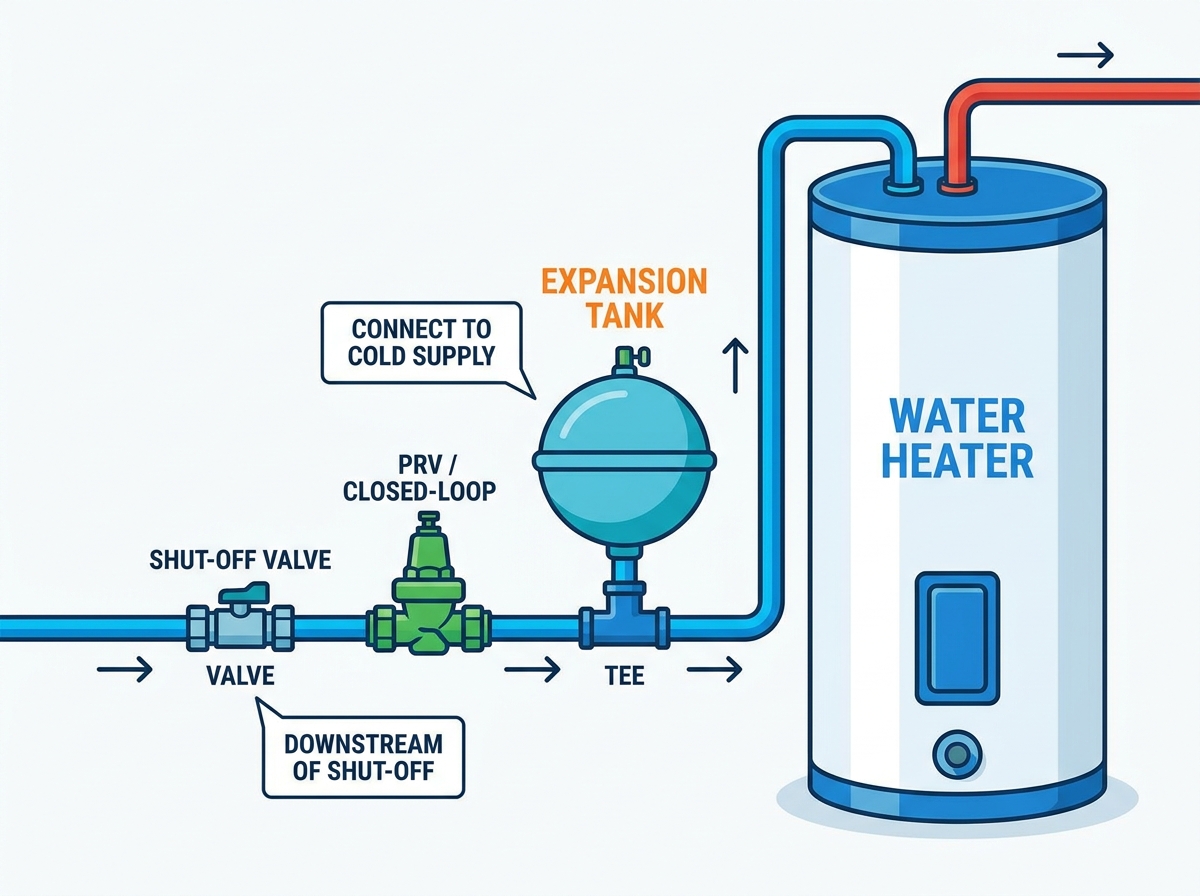
Location: The tank must connect to the cold water supply line, strictly downstream from the main shut-off valve and upstream of the water heater.
Support: A water-logged expansion tank can weigh over 20 pounds; using a Round Expansion Tank Bracket is critical to prevent pipe shearing.
Orientation: While some manufacturers allow horizontal installation, vertical (hanging down or standing up) is the industry standard to minimize stress on the connection point.
Prerequisite: The tank’s air pressure must be pre-charged to match the home’s incoming water pressure before installation.
You must identify the core connection point before making any plumbing modifications. Install the unit directly on the cold water inlet line. Municipal plumbing codes require specific placement for safety and optimal performance. You must position it carefully between the water heater and the cold water isolation valve. This isolation valve acts as your main shut-off point during routine maintenance. Placing the device here ensures it effectively absorbs excess pressure before the pressure damages the main heating vessel. Professional installers universally agree on this specific location.
Why does the cold line matter for overall system longevity? Hot water degrades the internal rubber butyl bladder much faster. Exposure to high temperatures makes the rubber brittle over time. Connecting to the cold side actively extends the operational lifespan. You save considerable money by avoiding frequent device replacements. A typical 50-gallon heating cycle creates measurable thermal expansion. Routing this expanded volume back into the cold feed prevents thermal shock to the bladder material.
Distance requirements also play a major role in pressure management. Plumbers ideally place the unit within 18 to 36 inches of the water heater. Proximity ensures the device effectively absorbs the immediate pressure wave. This wave generates predictably during every single heating cycle. If you place it too far away, pipe friction loss reduces its overall effectiveness. Follow these exact distance guidelines:
Measure 18 inches back from the cold inlet nipple to establish the minimum boundary.
Measure 36 inches back to establish the maximum boundary.
Ensure no other fixtures tap into the line between the device and the heater.
Once you locate the cold water line, you must choose an appropriate physical orientation. Vertical installation remains the highly recommended industry standard. Many professionals prefer the suspended orientation. Installing it dome down prevents air from getting trapped inside the water side of the bladder. This technique extends bladder life significantly. Alternatively, you can use the upright orientation. Installing it dome up remains perfectly valid if supported correctly. You must simply consider trapped air bleeding procedures during your initial setup.
Horizontal installation introduces surprisingly high risk. Let us look closely at the primary risk factor. When a butyl bladder eventually fails over time, the unit fills completely with water. A horizontal orientation creates a severe cantilever effect. This heavy, unbalanced weight pulls down sharply on the pipe threads. Over time, this leverage easily snaps copper or CPVC joints.
Manufacturer caveats exist regarding horizontal setups. Even if allowed by OEM manuals, local municipal inspectors frequently reject horizontal mounts outright. They require robust, specialized structural support to pass official inspection. Avoid horizontal mounts unless overhead clearance strictly demands it.
Choosing fittings requires careful attention to basic metallurgy. Use brass or stainless steel dielectric tees. You need these special fittings when connecting to copper or galvanized steel pipes. They actively prevent galvanic corrosion between dissimilar metals. Corrosion creates pinhole leaks and weakens the entire joint assembly rapidly.
Orientation Type | Mechanical Risk Level | Bladder Stress | Inspector Approval Rate |
|---|---|---|---|
Vertical (Suspended) | Low | Minimal | Excellent |
Vertical (Upright) | Low | Moderate | High |
Horizontal | Severe | High | Very Poor |
We need to look closely at the hidden weight variable. A standard two-gallon unit weighs roughly five pounds empty. You can easily hold it in one hand. However, it quickly exceeds 20 pounds when fully water-logged. This internal flooding happens naturally due to eventual bladder degradation. You must plan for this maximum weight scenario during installation.
You face severe risks with direct-to-pipe mounting. Do not rely solely on PEX, Copper, or CPVC piping. Standard plumbing pipes cannot safely hold a fully loaded, 20-pound dead weight. This structural negligence leads directly to stress fractures. It pulls solder joints apart and cracks plastic fittings. Eventually, you will face catastrophic pipe failure and costly interior flooding.
The optimal solution involves dedicated mechanical anchoring. You achieve permanent stability by securing the system using a reliable Round Expansion Tank Bracket. This eliminates the dangerous cantilever forces completely.
Evaluation criteria for brackets matter greatly. Look for heavy-duty galvanized steel construction. Galvanized metal resists ambient basement moisture and prevents rust. You want adjustable quick-release tension bands for simple future maintenance. Ensure the chosen bracket offers direct wall-stud mounting compatibility.
Implementation requires attaching the hardware properly. Secure it directly to a wooden structural wall stud. You can also strap it to the water heater casing itself using approved metal banding. This strategic support effectively isolates the delicate plumbing joints from harmful mechanical stress. It keeps the entire assembly rigid and secure for decades.
Many homeowners skip the most crucial preparation step entirely. The pre-installation rule is absolute and unforgiving. You cannot simply have the expansion tank connect to the plumbing network right out of the retail box. They require precise manual adjustment beforehand. Manufacturers ship them at a factory default pressure.
We use a simple, reliable pressure matching framework. Follow these sequential steps for optimal results:
Measure your incoming static municipal water pressure. You can easily do this using a basic hose bibb gauge. Attach it to an outside spigot. Open the valve fully and record the peak PSI reading.
Locate the air valve cap on the new device. Remove the protective plastic cover to expose the valve stem.
Grab a standard bicycle air pump equipped for Schrader valves. Attach the pump nozzle securely to the exposed stem.
Adjust the unit's baseline pressure. Manufacturers usually ship them pre-charged at 40 PSI. You must adjust this to exactly match your home's incoming pressure. Residential pressure typically ranges between 50 and 70 PSI.
Check the final pressure setting using a digital tire gauge for maximum accuracy.
Consider the severe outcome of skipping this vital preparation. Failing to match the pressure renders the entire device entirely useless. If the factory charge remains lower than your house pressure, municipal water simply crushes the internal bladder immediately. The bladder stretches too far and loses all elasticity. Alternatively, if you over-pressurize the unit, it remains completely rigid. It will fail to absorb any thermal expansion whatsoever.
Common Mistake: Never use an unregulated air compressor to charge the unit. Air compressors deliver air too rapidly. They easily rupture the delicate internal rubber membrane. Always use a manual bicycle hand pump for safe, controlled pressurization.
Understanding local regulations prevents costly rework and delayed property sales. The main code trigger applies to nearly all modern residential homes today. Most municipal codes (including the UPC and IPC) now strictly mandate these safety devices. Inspectors require them legally whenever a "closed-loop" plumbing system is created.
How do you reliably identify a closed loop? Look for the distinct presence of a Pressure Reducing Valve (PRV). Plumbers install PRVs near the main water shut-off to protect indoor fixtures from excessive street pressure. You might also find a backflow preventer or a simple check valve. Municipalities often install these directly at the main city water meter. These specific components block expanding hot water from flowing back out into the municipal city main.
Once you trap water between a PRV and your heater, you create a closed loop. As the heating elements activate, the water expands by up to two percent in volume. It has nowhere to go. This spikes the internal pressure past 150 PSI easily.
Follow this professional inspection checklist carefully to guarantee compliance:
Ensure the unit remains visually unobstructed for future testing. Inspectors and technicians need easy physical access to the bottom air valve.
Verify absolute clearance around the tension bracket bands.
Verify no extra valves exist between the heater and the device. Installing a random isolation valve right there creates a major safety code violation. Someone could accidentally close it, isolating the safety mechanism entirely.
Adhering to these strict municipal guidelines ensures your family remains safe from explosive pressure risks. It also guarantees a smooth process when selling your home or claiming warranty replacements.
Correct installation protects your expensive plumbing infrastructure from silent, daily damage. You must connect the device directly to the cold water supply line for maximum durability. Taking the time to accurately match the internal system pressure prior to final installation guarantees proper functionality. Utilizing proper structural anchoring prevents disastrous mechanical pipe failures down the road.
To move forward successfully, execute these specific next steps. First, measure your home's incoming static water pressure today using a standard bibb gauge. Second, procure the correct volume size based strictly on your heater's total gallon capacity. Finally, secure a high-quality mechanical wall bracket before beginning any plumbing pipe cuts. Following these rules ensures a leak-free, code-compliant result.
A: No. While technically it would absorb system pressure, the elevated hot temperatures rapidly degrade the internal rubber butyl bladder. This heat exposure causes premature material failure and immediately voids most manufacturer warranties. Always use the cold inlet line.
A: While it should ideally sit within three feet, it can technically be installed anywhere on the primary cold water supply line. However, you must ensure there are absolutely no shut-off valves or check valves installed between the tank and the water heater.
A: Generally, no. Tankless systems heat water strictly on demand without storing a large volume of heated water. However, you must check specific manufacturer specs and local codes. Closed-loop systems utilizing active recirculation pumps may still legally require one.


