
Views: 0 Author: Site Editor Publish Time: 2026-06-29 Origin: Site


Unmanaged thermal expansion silently degrades plumbing infrastructure over time. Left unchecked, rising pressure spikes often lead to premature boiler failure, blown seals, and instantly voided warranties. Water naturally expands when heated. This creates dangerous hydrostatic pressure within modern closed-loop systems. Understanding how to manage this physical reality prevents catastrophic leaks.
We provide a rigorous, code-compliant framework for connecting an expansion vessel. You will move beyond basic DIY advice to master professional-grade implementation. Successful installation relies equally on accurate pre-charging, secure physical mounting, and precise system placement. Plumbers routinely see systems fail simply because installers overlook these fundamental engineering principles. We aim to equip you with exact tolerances and proven methods to guarantee system longevity.
Pre-charging is non-negotiable: The vessel’s air pressure must match the incoming cold water system pressure before installation.
Physical support is critical: A water-logged vessel adds significant weight; utilizing purpose-built hardware like a Sealed Bowed Expansion Tank Bracket prevents catastrophic pipe strain.
Location dictates efficacy: Installation must occur on the cold water supply line, downstream of the pressure reducing valve (PRV) and upstream of the water heater.
Compliance mandates: Local plumbing codes dictate isolation valve usage and backflow preventer placement.
Heating water increases hydrostatic pressure. This physical reaction happens inside every closed-loop plumbing system. Water volume expands by roughly two to three percent when heated from room temperature to standard operating levels. This extra volume needs somewhere to go. Older plumbing systems functioned as open loops. Expanding water simply pushed back into the municipal supply. Modern systems use backflow preventers and pressure reducing valves (PRVs). These devices create a closed system. Expanding water cannot escape backwards. It presses violently against pipes and fixtures.
Omitting a vessel creates immense operational risks. The first symptom often involves the Temperature and Pressure (T&P) relief valve weeping. Many people mistake this weeping for a faulty valve. In reality, the T&P valve is acting as a critical safety net. Continuous weeping means system pressure has reached dangerous limits. Ignoring this leads to ruptured pipes and blown internal water heater seals. System life drops drastically. Boiler manufacturers routinely void warranties if they discover damage caused by uncontrolled thermal expansion.
You must determine your current system status before starting. Evaluating an open versus closed system is straightforward. Inspect the main cold water inlet. Look for a PRV or check valve near the water meter. If you spot either device, you have a closed system. You absolutely need an expansion vessel to absorb the pressure spikes.
System Status Identification Guide
Component Found at Water Main | System Classification | Vessel Requirement |
|---|---|---|
Pressure Reducing Valve (PRV) | Closed Loop | Mandatory |
Backflow Preventer / Check Valve | Closed Loop | Mandatory |
Straight Pipe (No valves) | Open Loop | Optional (Code dependent) |
Selecting the correct vessel volume requires basic math. You must correlate the water heater capacity in gallons or liters against your static water pressure. A standard 40-gallon heater running at 50 PSI needs a standard two-gallon vessel. A 75-gallon heater running at 70 PSI requires a much larger unit. Industry standards favor sizing up. When you fall between two sizes, always choose the larger volume. A larger bladder mitigates risk better. It prevents the internal diaphragm from stretching to its maximum limit during extreme heating cycles.
Inline-supported vessels fail at alarming rates. Installers frequently hang these heavy tanks directly from standard copper piping. A seemingly light two-gallon tank weighs over 20 pounds once water-logged. Copper joints eventually fatigue under this constant downward shear force. Threaded connections snap, flooding utility rooms instantly. You must transfer this load weight to a solid wall or floor joist. We recommend utilizing a Sealed Bowed Expansion Tank Bracket for structural integrity. This purpose-built hardware wraps securely around the cylinder. It completely removes the stress from the delicate plumbing fittings above.
Gather your essential tools before beginning. Missing components mid-installation causes immense frustration.
Calibrated water pressure gauge
Bicycle pump or portable air compressor
PTFE tape (Teflon tape)
Pipe joint compound (pipe dope)
Threaded brass tee fitting
Dedicated isolation valve
Pipe cutter and deburring tool
Structural wall bracket
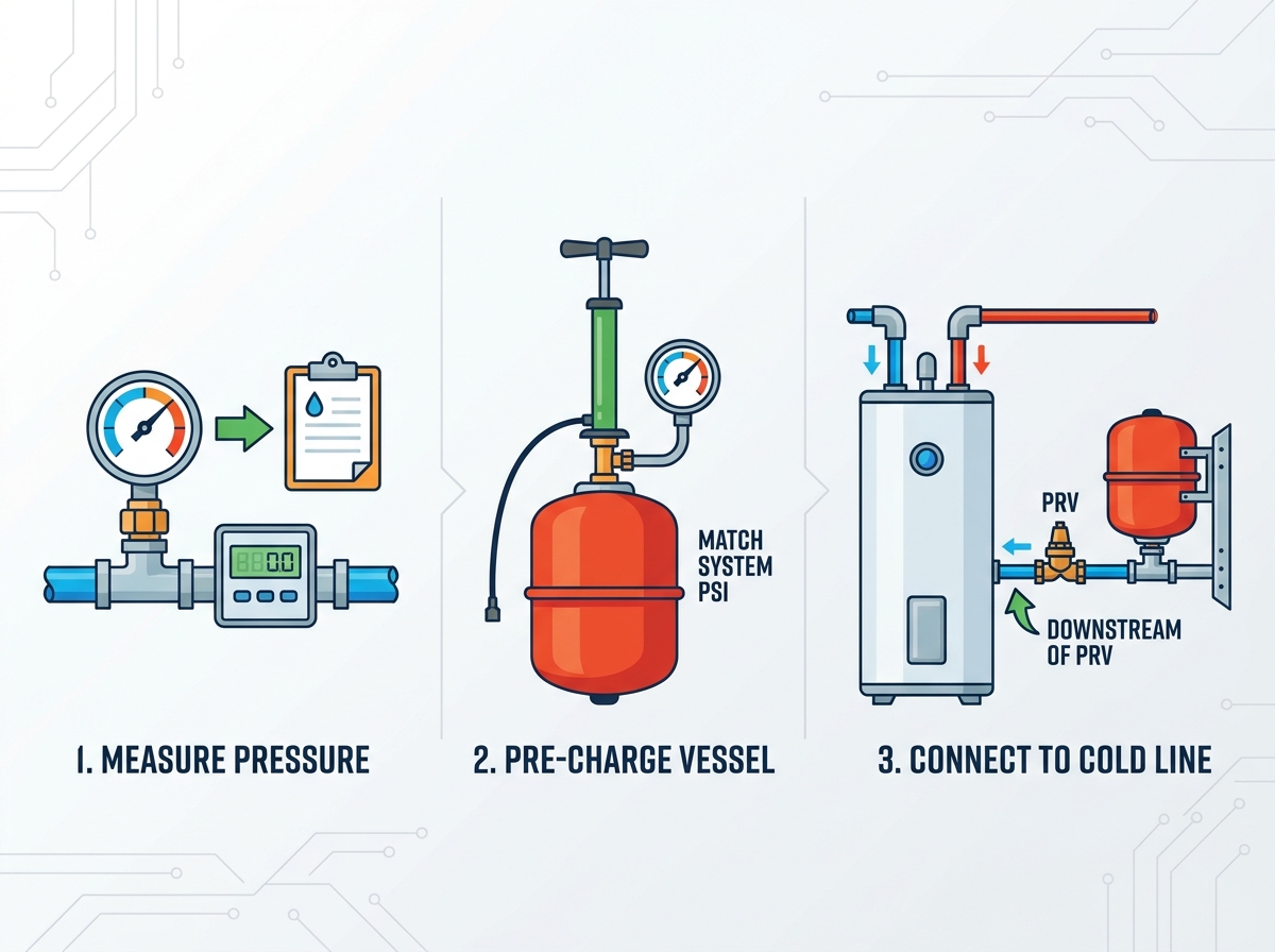
You must measure static pressure accurately. Locate a facility hose bib or drain valve close to the main inlet. Attach your water pressure gauge securely. Open the valve fully to register the incoming force. Leave it open for several minutes. Note the highest reading on the dial. This number represents your static system pressure. You will use this exact number to calibrate your equipment.
Adjusting the vessel requires patience. Every unit ships with a factory pre-charge, usually around 40 PSI. This factory setting rarely matches your actual home pressure perfectly. Locate the Schrader valve on the tank exterior. Remove the protective cap. Use a standard tire pressure gauge to check the internal air bladder. If your home pressure is 60 PSI, you must increase the bladder pressure to 60 PSI. Connect a manual bicycle pump or air compressor. Add air in short bursts. Re-check the pressure frequently. Match the bladder pressure to the incoming static pressure exactly.
Many novices test the air pressure after threading the tank onto the pipe. This results in false readings. Once connected to the water line, system water pushes against the bladder. The air gauge will simply read the water pressure pushing back. You cannot gauge the true air charge under these conditions. Failing to calibrate the tank uninstalled guarantees bladder failure. An unbalanced diaphragm stretches unevenly and ruptures prematurely.
System preparation determines your success. First, isolate the main water supply by shutting off the primary valve. Open the lowest sink faucet to drain residual system pressure. Next, identify the optimal insertion point. You must locate the cold water supply line. The ideal spot sits downstream of any PRV but upstream of the water heater itself. Ensure you have enough physical clearance to mount the unit safely.
Cut the Pipe: Use a specialized pipe cutter to remove a section of the cold water line. Clean the burrs inside the pipe thoroughly.
Install the Tee Fitting: Insert a threaded Tee fitting. Depending on your pipe material, this may require soldering copper or crimping PEX.
Integrate an Isolation Valve: If local codes permit, install an isolation valve directly above the Tee. This allows future tank maintenance without draining the entire building.
Mounting and threading require precision. Secure the tank against the wall using the designated wall bracket. Ensure the bracket grips the tank body tightly. Apply three wraps of PTFE tape clockwise around the male threads. Next, apply a thin layer of pipe joint compound over the tape. This double-seal method prevents micro-leaks. Thread the unit into the fitting by hand. Turn it until it feels snug. Finally, use an adjustable wrench to give it one more half-turn. Avoid over-torquing. Excessive force cracks brass fittings and destroys rubber gaskets.
Orientation sparks fierce debate among professionals. Some manufacturers allow horizontal installation. However, vertical installation hanging down remains the preferred industry standard. Hanging the unit vertically prevents air locking within the water chamber. It also reduces lateral shear stress on the fittings. Horizontal installations place uneven weight distribution on the internal bladder, shortening its lifespan considerably.
System re-pressurization requires a gentle touch. Go to the main water shutoff valve. Open it very slowly. Rushing this step introduces violent water hammer. Fast flowing water slams into the empty vessel, potentially damaging the internal bladder. Let the pipes fill gradually. Listen for air escaping from the open faucets you left running earlier. Once water flows smoothly from those faucets, turn them off.
Leak detection ensures long-term safety. Inspect every newly threaded joint with a flashlight. Wipe them with a dry paper towel to spot microscopic moisture. Next, conduct a thermal cycle test. Turn on the water heater. Let it reach its maximum set temperature. Monitor the system pressure gauge during this heating cycle. The pressure should remain entirely stable. If pressure spikes drastically, your pre-charge calculation was incorrect or the bladder is defective.
Online forums highlight common implementation mistakes repeatedly. Avoid these frequent errors to ensure compliance:
Installing on the hot water line: Hot water degrades the internal rubber bladder rapidly. Always install on the cold supply side.
Ignoring micro-leaks at the Schrader valve: Installers often forget to check the air valve post-charging. Apply a drop of soapy water to the Schrader valve. If bubbles form, tighten the core.
Skipping structural support: Hanging tanks entirely by their threads invites structural failure.
Knowing when to hire a professional protects your property. Simple threaded connections on accessible PEX tubing favor DIY work. However, you should hire a certified plumber for complex scenarios. If the job requires soldering large-diameter copper pipes in tight spaces, call a pro. Commercial environments also dictate strict code compliance. Professionals understand exact backflow preventer placement rules and mandatory isolation valve regulations unique to your municipality.
Connecting this equipment remains a strict exercise in pressure management and physical security. You cannot afford to skip calibration or rely on weak pipe fittings for support. Master these engineering principles to protect your entire plumbing infrastructure from thermal damage.
Actionable next steps to ensure success:
Purchase a reliable water pressure gauge immediately.
Measure your baseline static pressure before buying any parts.
Acquire the correct structural mounting bracket to eliminate pipe stress.
Verify your local plumbing codes regarding isolation valves before cutting any pipes.
A: While some manufacturers allow horizontal installation, hanging it vertically downward is optimal. Vertical orientation prevents internal air locking. It also significantly reduces lateral shear stress on your plumbing fittings. Horizontal setups wear the bladder unevenly over time.
A: Perform the tap test. Tap the top half and bottom half of the tank with a metal tool. Both sides should sound hollow. If the air side produces a dull thud, the tank is water-logged. Water leaking from the Schrader air valve also confirms catastrophic bladder failure.
A: Install it on the cold water inlet line. It must sit downstream of any backflow preventer or pressure reducing valve, but upstream of the water heater itself. Ensure enough physical clearance exists for secure wall mounting.
A: Yes. Factory pre-charges rarely match specific residential or commercial system pressures perfectly. Manual calibration is almost always required. You must match the internal air bladder pressure to your exact incoming cold water static pressure before connecting it.


